|
SketchFlat: 2d CAD, with Constraints |
|||||||||||||||||||
|
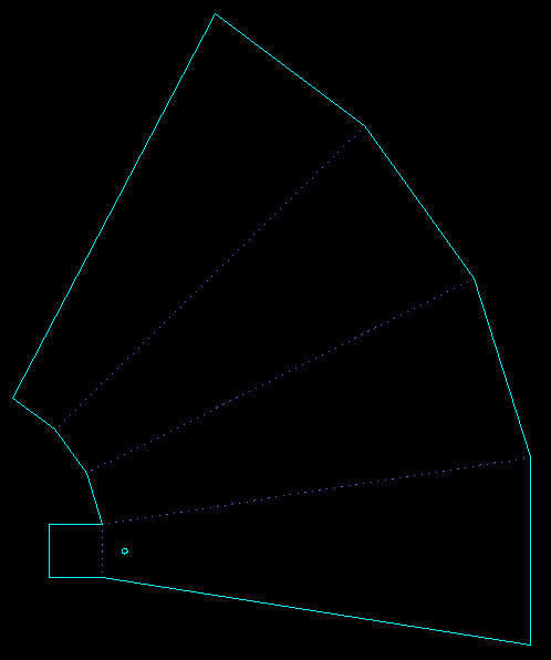
This program is obsolete; SolveSpace replaces it completely, and is now available as free software. * * * SketchFlat is a two-dimensional technical drawing program. It is designed primarily to generate CAM output data, for manufacturing on a laser cutter, waterjet machine, vinyl cutter, 3-axis mill, or other machine tool. Consider the part shown below:
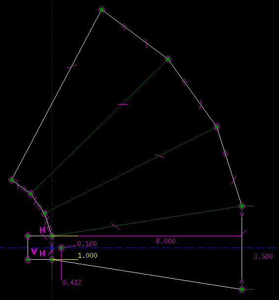
This is a microwave horn, flattened out. I will cut along the solid lines, and fold along the dashed ones. (I'll make this on a laser cutter, from very thin metal sheet. I would like to score the fold lines, but lasers don't do that, so instead I will perforate them. The dashes are not just cosmetic.) This will produce a square horn, tapering from 1.000" across at the narrow end, to 3.500" at the wide end. The narrow end is closed, but the wide end is open. The length, measured along one of the trapezoidal faces of the horn, is 8.000". (The distance along the horn's axis is a bit shorter, of course.) There's a circular hole 0.412" from the back face, for the feed; this hole is 0.100" diameter. I might have hand-calculated the geometry to produce this template, and drawn it in any tool, by typing in coordinates. Instead, I drew the part in SketchFlat:
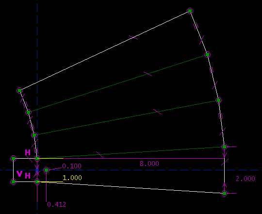
The dimensioning here is fully parametric: there is a simple mapping between the specifications of the part and the numbers that I type in to the drawing. Let us say that I change my mind; the wide end is currently 3.500" across, but I would rather have 2.000". I will type in the new dimension:
In order to produce our new horn, many different lines had to move; but SketchFlat recalculated the geometry automatically. This makes it easy to make changes. It also makes it easy to draw the part in the first place, since no hand-calculation is required; SketchFlat translates the specifications into (x, y) coordinates for each line segment in the sketch. The program is able to do this because the part is described in terms of dimensions and other geometric constraints. The magenta marks describe these constraints. For example, the two inward-facing arrows at the far right of the drawing indicate a `symmetry' constraint: the endpoints of that line segment are symmetric about the dashed blue reference axis. The H and V characters indicate horizontal and vertical line segments. The tick marks indicate equal-length line segments. Many different combinations of constraints would describe the geometry of this part; so as we constrain the part, we have many different choices available. We will try to choose dimensions that reflect the design intent; that is, we will try to draw constraints that correspond naturally and in a simple way to the specifications that we are given. Feature ListIn the example above, we were mostly just drawing line segments, but many different types of sketch entity are available, including:
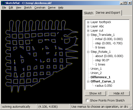
A datum is a line, point, or curve that will not appear in the exported geometry (i.e., it's not a line that we eventually want to cut with the laser). It's often helpful to draw extra lines and points and curves, in order to construct some more complex geometric relationship. You can do this using datum lines and points, or by marking any other entity (line segment, circle, etc.) as `construction'. A sketch consists of some combination of these entities. These entities are drawn on layers. Each layer may be exported directly, or it may be used in `derived operations', to obtain more complex polygons. If our part is `a rectangular plate with a circular notch', then it might be simplest to draw the rectangle on one layer, draw the circle on another, and then take the Boolean difference. Derived operations include:
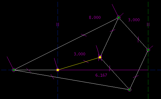
Once a part has been drawn, it may be exported as a DXF, as HPGL, or as G-code. All curves are broken down into piecewise linear segments before output is generated, so the structure of these files is very simple. ComparisonVersus a typical vector drawing program (Adobe Illustrator, CorelDRAW, etc.): SketchFlat does not have any graphics features. It makes no provision to specify with what color a line should be drawn, or to fill a polygon, or to apply any raster-type effects. (This makes sense, because these features are not meaningful when you are producing vector CAM output.) SketchFlat does provide parametric dimensioning, which drawing programs don't. This is useful when entities in a drawing should have some exact geometric relationship (e.g., line A is thirty degrees clockwise from line B), and are not just drawn by eye with the mouse. Versus a typical sketch-based 3d CAD program (Pro/E, Rhino, Solidworks, Autodesk Inventor, etc.): Sketchflat has no 3d features. Sketchflat is roughly equivalent to any of these program's sketcher (i.e., to the portion of the program where a two-dimensional section is drawn, that will later be swept or extruded to produce a three-dimensional solid). Depending on the 3d CAD tool, SketchFlat's parametric dimensioning may be more powerful. SketchFlat has some elementary `derived' operations, to fill in for operations (like rounding corners) that would typically be performed on the solid model, and not in the sketch. Versus a typical 2d CAD program (AutoCAD, etc.): SketchFlat does not have the hierarchy and structured document features that most of these programs offer. It is therefore unsuitable for drawings containing a large number of entities. SketchFlat does not have features to indicate how lines are displayed (thickness, color), which makes it unsuitable for producing human-readable output. SketchFlat does provide complex parametric dimensioning. I've seen parametric features or add-ons for some 2d CAD software, but only in basic form (only the `acyclic dependency graph' kind; refer to my description of SketchFlat's internals to see what this means). Once a part has been drawn, SketchFlat's `offset curve' tool may be used for basic cutter radius compensation. This might in some cases make it possible to live without separate CAM software. Sample SketchesAn `easy' demonstration: Napoleon's theorem. (It's easy because you can solve the sketch while considering at most two equations at a time.)
A `harder' demonstration: Peaucellier's linkage for straight-line motion. (It's harder because the solver must consider many equations simultaneously.) As the highlighted link rotates around the origin, the rightmost point moves along the green vertical line. The right endpoint of the highlighted link may be dragged with the mouse.
(SketchFlat can solve arbitrary planar linkages. A sketch with only distance and point-coincident constraints is a linkage; the distances are the lengths of the links, and the coincident points are the pivots. The solver can quickly determine (a) whether the linkage can be assembled at all, (b) how many degrees of freedom the finished linkage will have, and (c) the positions of all of the links, as one or more of the links is dragged. Linear slides are also possible, in the form of point-on-line constraints.) A `hard' demonstration: A twelve-sided regular polygon. I drew a twelve-sided polygon. I then used equal-length constraints to force all its edge lengths to be equal, and constrained all its vertices to lie on a circle. This requires the simultaneous solution of 22 unknowns.
A Euro (currency) symbol, in terms of its official geometric definition:
InternalsI've used Pro/E extensively, so SketchFlat is to a certain extent inspired by Pro/E's sketcher. Like Pro/E, I use a numerical method to solve many nonlinear equations simultaneously. This permits me to accept a wide variety of constraints; SketchFlat will readily solve many high school geometry problems. I've seen other commercial tools that can't do this. SketchFlat is built around a trivial symbolic algebra library. The geometry of entities—like lines or splines or circles—is described in terms of those symbolic variables. For each constraint, SketchFlat writes a symbolic equation. `Easy' constraints are solved by symbolic forward-substitution on the system of equations, to reduce the number of unknowns. The system of constraint equations is then partitioned into the smallest consistent subsystems we can find, and each subsystem is solved using a multivariable Newton's method. If the system is underconstrained (i.e., if we can find an infinite number of solutions that still satisfy our constraints), then we will automatically make assumptions, until we have restricted ourselves to a single solution. If the system is inconsistent (i.e., if we can prove that no solution satisfying the constraints exists), then we will report this, and indicate which constraints should be removed to bring the sketch back to consistency. A longer description of SketchFlat's internals is available:
Limitations, and Future EnhancementsThis is the first release of SketchFlat. I don't know of any actual bugs, but I expect that several areas will later be improved:
Other defects may exist; please contact me if you find one. DownloadThe program is written for Win32. I develop under XP. I expect but have not tested that it will work under 95 and later. There is a single .exe file to download:
There is no installation program; just save it somewhere and run it. There's no manual, but I have a long tutorial. The source code is also available for download. This program may be distributed and modified under the terms of the GPL Version 3.
Oct 2007, Cambridge MA |