|
Demo: Cloning a Verichip Yourself |
|||||||||||||||||||
|
I used a relatively sophisticated piece of electronics to clone a Verichip. This made things trivially easy. Even though I had never seen a Verichip before in my life, I just had to write a hundred lines of code; but because I used my proxmarkii, I've heard claims that it is impossible to talk to a Verichip without expensive equipment. I therefore wanted an inexpensive cloner, with decent read range and a simple user interface. It should be easy to build, and it should not require a PC to operate. This will make it easy for anyone to clone a Verichip themself, without spending a lot of money. It's also a neat demonstration of just how much a low-end microcontroller's peripherals can be twisted to do.
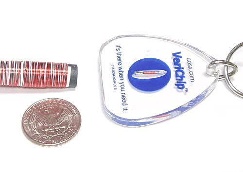
This device can read and replay a Verichip's ID. If you can get the antenna close to your victim's shoulder, then your circuit board is electrically indistinguishable from their implanted chip forever after. Full schematics and documentation are given below. The total parts cost is under twenty dollars, and you can get everything except the antenna from Digikey. The antenna must be wound on a ferrite rod, of the type available from CWS Bytemark and others. The utility of this device is limited, because the Verichip is not heavily deployed. As of this writing, you can use your cloner to:
Please tell me if you know of any others. You might eventually be able to impersonate an American soldier, or to commit immigration fraud, but this is not yet possible.
A similar technique might be used to make an `American soldier detector'. There you would not necessarily be looking to get the ID off the Verichip, whose read range is much too short for that to be practical, but just to detect its presence. This is an easier problem, similar to the theory of operation of anti-shoplifting tags. (In normal operation, energy couples into the Verichip's antenna, and powers some electronics inside the tag. These electronics transmit the tag's ID to the reader. The reader normally looks for that returned signal. Instead, we could just look for the antenna resonance. This greatly increases the `detect range', since there's no longer any need to power up the tag's electronics.) Assembling the DeviceI would not expect any purchasing issues; the parts that I chose are very common and available. The bill of materials lists Digikey part numbers for everything, in addition to manufacturer part numbers and part values for the passives (resistors, capacitors). Alkaline AAA cells are best; with moderate use, these should last for a very long time. It is possible to build this circuit by soldering wires from point to point. I don't recommend it, unless your time is worth nothing; printed circuit boards were invented for a reason. I have board artwork available for download. I bought my boards from MyroPCB, but the design rules are extremely loose (12/12 thou); you could even use one of those terrible iron-on methods, and do it yourself in your kitchen. If you don't need silkscreen and soldermask (the white lettering that tells you where the parts go, and the green stuff that stops traces from shorting to each other when you glob solder on them), then PCBExpress can get you two boards for sixty dollars, which isn't terrible. This price is almost all setup fees, though. From Myro, the per-unit cost is around fifty cents, in large volume. I recommend that you socket the PIC, just to make it easier to rule out a bad micro if you have to debug. If you are using in-circuit programming, though, then there is no absolute need to. I recommend that you use an in-circuit programmer, like you can buy from Olimex and many others. This permits you to update the code on your PIC without removing it from the printed circuit board; the programmer connects to SV2, and can reach in and reprogram things from there.
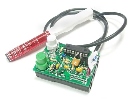
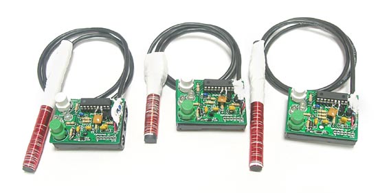
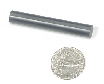
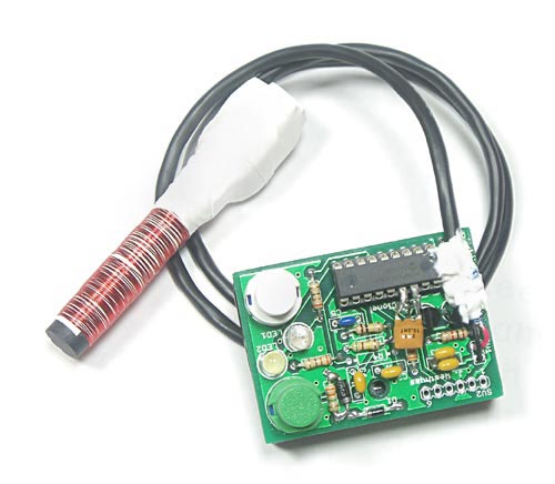
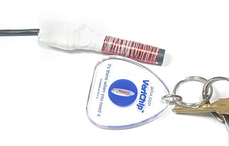
The antenna is a coil of wire on a ferrite rod; you have to wind this yourself. I recommend that you use R-037300-61 from CWS Bytemark. Many others will work, but a different number of turns will be required. Wind a single layer of 140 turns of #30 (AWG) magnet wire. This connects on SV1; you can solder the magnet wire directly to the board, but it's also okay to connect it through a reasonably short (< 2', say) piece of twisted-pair or coax. (I am not specifying twisted-pair or coax because you need a transmission line with a consistent characteristic impedance—you don't, it's low frequency, and everything is well-described by lumped element models. It's just that these will have more consistent parasitic L and C as the cable is flexed, coiled, etc. than if you used any old wire.) If you don't buy the thermal-stripping (i.e., the solder melts the insulation right off) kind of wire then it will be a pain to make the connections. Try removing the insulation with sandpaper, or scraping it with a knife. A sharp knife works best for me. If you want to get good read range, then you will have to tune your antenna. You can do this with only a digital voltmeter, though. Once you have assembled your device, install the batteries, connect the antenna, and press the white button. This will energize the antenna; you can measure the amplitude of the sinusoidal carrier being transmitted by measuring the DC voltage from the cathode of D1 to ground. This should be at least eight volts or so, before you start tuning, more if you're lucky. Remove a turn from the antenna coil. Straighten out the wire and keep it as far away from the antenna as you can. Watch that voltage as you do so; it should go up, at a rate on the order of a volt per turn. If it goes down then you've wound too few turns. In that case you must start over, and wind more turns this time (or splice a bit more wire on, but that is ugly). As you remove turns, the antenna voltage will start to increase much faster, and then start to decrease. Add turns until you reach the maximum again. At that point you have tuned the antenna to resonate at our transmitted carrier frequency. (By the way, there's no electrical reason to tune by slowly removing turns instead of by slowly adding them. It's just that it's easier to start with a long piece of wire and cut it shorter than to start with a short one and stretch it.) With the recommended ferrite and wire gauge, you can expect at least 80 V from the cathode of D1 to ground when the unit is properly tuned. Be careful not to tune your unit up too well. It's not easy, but with the proper ferrite (Material 61), you can get the voltage at the cathode of D1 above 130 V. At that point D2 will clamp the voltage across the tuning cap, neatly removing the modulation that contains the signal that you were looking for...
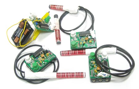
Try not to touch the windings of the antenna with your fingers. If you do then a small amount of the current through the magnet wire will couple capacitively to your fingers, through the insulation, and detune the coil. This will decrease your read range. Despite the high voltage (~160 V peak-to-peak), there is not a very major safety issue: just touching the wires will detune the circuit, and greatly reduce the voltage before it has a chance to do harm. The printed circuit board is exactly the size of the 3 AAA batteries. It is designed to be mounted on top of the plastic battery case, and I did so using electronics grade noncorrosive silicone (GE 162). Hot glue or epoxy (or nothing; the soldered leads hold it fairly well) would be fine, though. It's important to deflux the board before sealing it up; clean it thoroughly with flux remover (typically some nasty chlorinated hydrocarbon), or failing that with alcohol. This circuit has high-impedance nodes very close to hundred-volt carriers, so it's important to get rid of any leakage paths along the board. No-clean flux is probably asking for trouble here. Note the ugly rework in the pictures shown above. I made some mistakes in the rev 1 board artwork, as described below, and I have not yet paid to get new boards manufactured. I just flywired the changes (add ceramic resonator U1, add Zener diode D2) as best I could. Theory of OperationPlease refer to the schematic. It's important to remember that I designed this device for absolute minimum parts count and cost. I therefore made some fairly disgusting tradeoffs. A lot of what I did is terrible design practice. I had originally intended to use the PIC with an ER (external resistor) oscillator. It's okay for the clock frequency to drift within a few percent, since the tag always synchronizes itself off the reader's clock. It therefore seems like there's no reason to spend money on a crystal. This turns out not to be true, though. The phase noise of the ER oscillator is terrible. I 'scoped the CLKOUT pin, with the oscillator running at 10 MHz (so CLKOUT is around 10/4 = 2.5 MHz), and triggered off an edge of that square wave. Using the delayed timebase, I looked at an edge about 100 us after the trigger point; it jitters over more than a period! The frequency-selective antenna turns this phase noise into amplitude modulation, which raises the noise floor to a hopeless level. I therefore cannot use the ER oscillator. The INTRC oscillator is somewhat better, but does not divide well to produce 134 kHz (125 kHz or 143 kHz, large error). This means that we need to use a crystal or a resonator; either will give good enough phase noise, and a resonator's cheaper. I chose a 10 MHz ceramic resonator, for thirty-five cents.
The Verichip is designed to be read at 134 kHz, so we will divide our instruction clock by 19 to produce a 132 kHz carrier to transmit. This isn't quite right, but it will be close enough. When we are reading a legitimate Verichip (i.e., pretending to be a reader, to clone someone's implant), the tag will derive its timing from the carrier that we transmit. That means that it doesn't matter if we're a little bit off, because the tag will be off by that same amount. When we are being read by a legitimate reader (i.e., pretending to be a tag, to pretend to be someone whose tag we've already cloned), we will derive our timing from the carrier that the reader transmits, which we measure through R9. In `read' mode, we transmit the unmodulated carrier that powers the tag. This means that we need a high-power output buffer to drive the antenna. This is all very low-frequency, so a couple of general-purpose transistors (Q1, Q2) will do the job fine. They are configured as emitter followers here, to buffer the carrier output by the PIC's GPIO pin. The GPIO pin can only source or sink +/- 20 mA; the transistors that we are using are rated for 200 mA, although we won't run them quite that high. The information-bearing signal returned from the tag appears in the voltage across C1, but we first have to separate it out from the carrier that we are using to power the tag. We do this with a peak detector, followed by a passive filter (D1, C3-5, R5-8). This produces a signal that we interpret using the PIC's comparator. I do this in a somewhat ugly way. The signal from the antenna is AC-coupled so that it has a mean of zero volts (with respect to ground). I apply this to one input of the PIC's comparator; the other input of that comparator goes to ground, through the VREF module. This means that I am applying an input voltage below Vss to the PIC, which is outside the recommended operation conditions. It works very well, though. The only problem is if the signal from the tag gets very strong, because the protection diodes will clamp it asymmetrically about ground, and move the decision point. It's difficult to couple to the tag's antenna well enough for this to be a problem, so I'm not very worried. Since I don't know very much about the structure of the tag's ID, it's difficult for me to come up with a good metric to determine whether I've read a valid ID. There is presumably a CRC or something, but I haven't bothered trying to figure it out; I have only a very small number of tags to test against, so it would be difficult for me to test any theory that I might come up with. Instead I just read the ID several times, and verify that it is the same each time. The current firmware reads the ID once, and then checks it three times. This is a parameter that you can play with; more verifications gives increased confidence in the ID, but also makes it more likely that we will reject a valid read. In `simulate' mode, we listen for a carrier from a reader, and change the load across the antenna in such a way as to transmit our ID. We can change the load across the antenna by either driving or tri-stating RB3. When we drive RB3 low, we short-circuit the coil through Q2. When we tri-state RB3, it cannot supply any base current for either Q1 or Q2, so no collector current flows, so the coil is open-circuited. The only trick is that we must listen for the legitimate reader's incident carrier, because that is what gives us our sense of time. We do this through R9, once again using the PIC's comparator. The resistor is necessary because the voltage at the antenna might be much larger than the PIC's Vdd = 4.5 V; without the resistor, a very large current would flow through the protection diodes on that input pin and destroy the microcontroller. R9 limits that current to a safe amount. Some current does still flow through the protection diodes, though; if R9 gets too small then we risk putting the PIC into latchup, which would be relatively bad. Also, comparator 1 stops working if too much current flows into the substrate from RA0. This is well outside the manufacturer's recommended operating conditions. Without R6, the current through the coil would drop to zero when we tri-stated RB3, which means that the current through C3 would drop to zero, which means that the voltage across it would drop to zero and we would lose our sense of time. As long as some current always flows, this isn't a problem. The device has no on/off switch; this is achieved in software. The PIC can be put to sleep (clock oscillator stopped, wake up on interrupt), dropping the micro's power consumption to almost nothing. The LEDs must be turned off, and the coil must be driven low (since the input buffer for RB3 might draw class A current if we float it, and R6 will draw current if we drive it high). The PIC's comparators and VREF module should be turned off; otherwise they burn about a hundred microamps. With the software given below, battery standby life should be on the order of the shelf life of the cells. DemoTo steal someone's Verichip: Press and release the white button. The white light will turn on while we try to get a read. Hold the antenna very close to the bearer's arm; if you know the orientation of the implanted tag, then try to hold your antenna parallel. The green light will blink to indicate a successful read, and the cloner will exit `read mode.' Press the green button to exit `read' mode without a successful read.
To replay the ID to a reader: hold the antenna close to the Verichip reader. Press and hold the green button until the door opens (or they bring you a drink, or they let you in to the army base, etc.). The green light will turn on for as long as you hold down the green button. The cloner looks like the cloned Verichip only while the green switch is depressed; the reader won't see you unless you're holding it down.
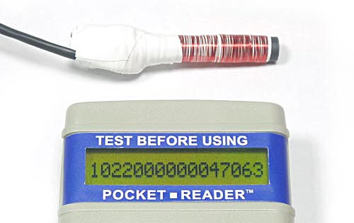
If you've got an ID that you would like to hold on to, then press the white button and then the green button, and then release both (in either order). This will save the most recently-read ID to the PIC's non-volatile (EEPROM) memory. The ID stored in EEPROM is loaded at power-on reset, so you can later recall this ID by removing and reinserting the batteries. By default, the stored ID is Annalee Newitz's, number 47063. The easiest way to archive an acquired ID (for later use, or to email to a friend, or whatever) is to read out the PIC's EEPROM, using the in-circuit programming connector. This can be saved as an IHEX file, or in any other format that your programming software supports. When it comes time to reuse that ID, just program it into the PIC's EEPROM, and it will be the first ID in memory after power-on reset.
The read range, when stealing someone's Verichip, is about an inch. This isn't great, but probably enough to work with. The official Verichip reader gives about four inches of read range, on axis and with fresh batteries. I could presumably do as well or better, but that would require more than one IC, and would therefore not be quite so cheap, or easy to build. If anyone from Verichip makes an issue of this, then I will design a `low-frequency range extension' board for my proxmark3, and see how far I can go. DownloadI have:
The board artwork is actually untested, but I am very close to sure that it is right. The software given above supports just Verichips, but it would be possible to modify it to work with certain proximity cards, using identical hardware. September 2006, Cambridge MA |