|
SketchFlat Tutorial |
|||||||||||||||||||
|
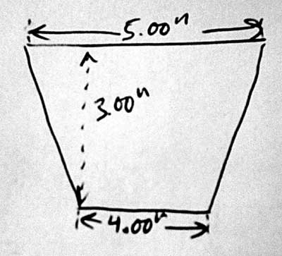
Parametric CAD tools are notoriously difficult to use. A lot of this difficulty is essential; no matter what the software does, it can't save you from understanding the geometry. This tutorial is therefore very long, even though we are drawing a trivial part. Many of the issues discussed here are not specific to SketchFlat. They would apply for any CAD tool, or even for a drawing that is dimensioned by hand. On the drawing, the part is described with dimensions. A dimension might indicate the length of an edge, or the angle between two lines, or some other geometric relation (e.g., that two circles are concentric). Given enough dimensions, the part is completely described. It's typical to make the drawing approximately to scale, to give the viewer some rough idea of what the part is supposed to look like, but that's just a courtesy. The dimensions alone must describe the part completely. ObjectiveWe will start with a rough sketch of a part, and draw it in SketchFlat. We will then export this drawing as a DXF. From there, we might send it to a laser cutter, or to some CAM software for toolpath generation, or to some other CAD tool. This is our part:
I'll call it a trapezoid. (The word trapezoid has multiple definitions. Here, I will use it to describe a four-sided polygon, with two edges parallel and the other two equal in length.) The two parallel sides are horizontal; the bottom one is four inches long, and the top one is five inches long. The trapezoid's altitude (i.e., the distance between the two parallel edges) is three inches. Of course, nothing in my pencil drawing says explicitly that the top and bottom edges are parallel, or that the left and right edges are equal in length. For a human-readable drawing, we can assume that they are. When we draw the part in SketchFlat, we will have to specify this explicitly; the software cannot guess our intent. Reference Coordinate SystemI start with an empty sketch. The sketch will always contain two datum lines. These lines intersect, and their intersection is marked with a datum point. A datum line does not have endpoints; it is infinitely long. In SketchFlat, datum lines are drawn dashed. One of the datum lines is horizontal, and the other is vertical. The point is drawn as a filled square.
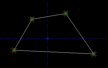
These are our references. Everything in the drawing will be dimensioned with respect to these two datum lines and that point. These references form a coordinate system; the horizontal line is the x-axis, the vertical is the y-axis, and the point is at the origin. It's not possible to move or redefine the references. The references (and only the references) are drawn in blue; other datum entities, that you can define yourself, are drawn in green. Ultimately, the coordinate system in which the part is described will have physical meaning. The axes might correspond to the physical axes of a CNC machine, and the origin to the machine's `home' position, as measured with limit switches. When we're drawing the part, though, we can probably choose the coordinate system for our own convenience, and rotate or translate the part as needed before exporting the file. (In SketchFlat, you can do that using a derived operation.) A good choice of position and orientation will make the part easier to draw. If the part has symmetry, then we might be smart to draw it symmetric about one of the coordinate axes. In general, there will be many different ways to draw and dimension a part; the choice is subjective. A careful choice of dimensions will clearly show the design intent. Our dimensions are given in inches, so we should work in inches. SketchFlat can work in either inches or millimeters, and you can switch between the two freely. Choose View -> Dimensions in Inches, if it isn't selected already. Inch dimensions are always given with three digits after the decimal point (e.g., 1.500). Millimeter dimensions are given with two (e.g., 38.10). Sketching the PartTo start, we will draw a quadrilateral. SketchFlat provides various geometric primitives, including line segments, circles, arcs of a circle, and cubic splines. In this case, we want four line segments. In SketchFlat, choose Sketch -> Line Segment, and then click somewhere on the drawing to start the line. Click three more times, to create the four line segments. Before clicking the fifth time, move the mouse pointer over the first point that you drew; this point will be highlighted yellow. Then click the mouse; SketchFlat will automatically constrain the lines that you just drew into a closed polygon, and stop drawing.
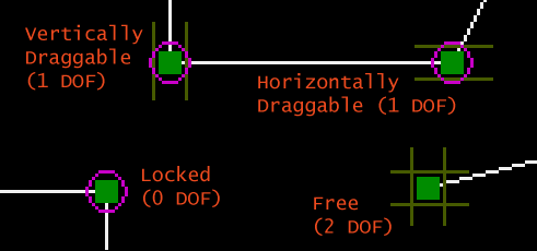
(So you've actually just drawn four line segments, and four point-coincident constraints, that constrain the line segments into a closed polygon. You could have drawn the four lines separately, and then added the constraints explicitly yourself—to stop drawing lines before you've made a closed figure, hit Escape. But here, it's quicker to let SketchFlat add the constraints automatically.) You can pan the viewport by center-dragging with the mouse, and zoom with the scrollwheel. To re-center and re-zoom to make your sketch fill the window completely, choose View -> Zoom To Fit, or press `F'. The small magenta circles represent the point-coincident constraints. If you drag one of the points, then the figure will stay closed, because it is constrained that way. But aside from that, there are no constraints; you can drag those four points anywhere that you want. This freedom is indicated by the dark yellow tic-tac-toe marks around each point. The vertical marks indicate that the point can be dragged vertically, and the horizontal marks indicate that the point can be dragged horizontally. In this case it has both, so the point has two degrees of freedom.
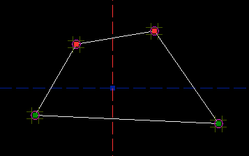
Once we start adding constraints, a point might have one or zero degrees of freedom. A point with one degree of freedom will move, but only along some line or curve. A point with zero degrees of freedom is locked, and won't move at all. Constraining the PartI tried to draw my trapezoid approximately right, but it's not perfect; to get the shape that we want, we must add our constraints. To start, we observe that the finished trapezoid has one axis of symmetry. In this case, I will choose to draw it with the vertical reference axis as the axis of symmetry. So we want to add a symmetry constraint. Hover the mouse over the top left point, until it is highlighted in yellow; then click to select it. The point is now highlighted in red, to indicate that it is selected. Repeat this for the top right point, and for the vertical reference axis.
Then choose Constrain -> Symmetric, or press `Y':
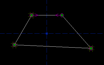
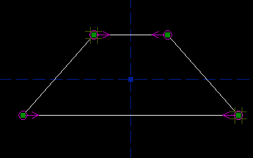
This constrains those two points to lie symmetric about the vertical reference axis. (So if you printed out the drawing, and folded it along the axis, then the points would be on top of each other.) The constraint is indicated by the two magenta arrows. The top left point still has two degrees of freedom, as indicated by the tic-tac-toe marks, but the top right point has none; the symmetry constraint forces its position. If you drag the top left point with the mouse, then the top right point will also move, in order to satisfy the constraint. (Depending on whether you drew the quadrilateral clockwise or counter-clockwise, either the top left or the top right point might be free. Look at the tic-tac-toe marks to see which one you can drag with the mouse, or look at the `Assumed Parameters' list in the panel on the right. The label above this list is yellow, because there are still unconstrained degrees of freedom.) Repeat the process for the bottom two points, and add another symmetry constraint. Now another point is fixed, in this case the bottom left one; if you drag the bottom right point, then the bottom left will follow. Our quadrilateral is now constrained to be a trapezoid:
Its rotation is fixed; the two parallel edges must be parallel to the horizontal reference axis. Its horizontal position is fixed, by the symmetry constraint, but its vertical position is free; you can drag it wherever you want in that direction:
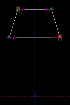
To constrain its vertical position, we might constrain one of the bottom points to lie on the horizontal axis. Select the bottom right point, and the horizontal axis. They now appear highlighted:
Choose Constrain -> Coincident / On Curve, or press `O'. This constrains the bottom right point to lie on the line. The bottom left point moves as well, because the symmetry constraint still applies:
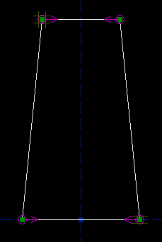
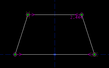
The top left point may be dragged freely; it still has two degrees of freedom. The bottom right point now has only one degree of freedom, its horizontal one; the vertical degree of freedom is restricted by the point-on-line constraint. The other two points are fixed, with no degrees of freedom. Constraints remove degrees of freedom. Most constraints remove one degree of freedom from the sketch, though some remove two. So our trapezoid still has three degrees of freedom. We might further constrain it by specifying the length of the top edge. Select the top edge, and then choose Constrain -> Distance / Diameter. This constrains the length of the top edge; the constraint is indicated by a magenta label drawn on the sketch. As we drew it, the top edge is 2.444 inches long. (The label isn't in a very convenient place. If you hover the mouse over the label, until it is highlighted, and then drag it, then you can put the label wherever you want.)
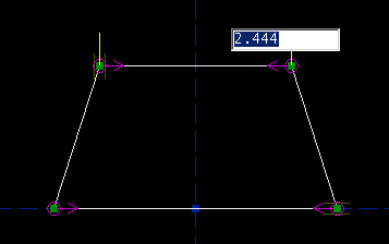
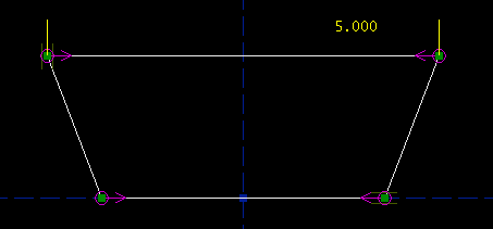
From our specification, this edge is supposed to be five inches long. To change the length, double-click the label. A text box appears on the sketch. Type the new length, and hit Enter. The length of the line changes, to respect the constraint; of course, all of the old constraints are respected too.
Repeat the process for the bottom edge, and constrain that 4.000 inches long. We're now down to one degree of freedom. This is good, because we have exactly one specification left, on the altitude between the top and bottom edges. Select those two edges:
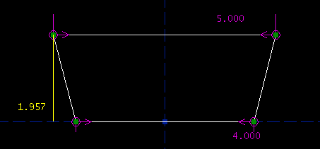
Then, choose Constrain -> Distance / Diameter. As before, the distance constraint is indicated on the sketch, by the label; right now the two lines are 1.957 inches apart.
As before, you can type in the desired altitude, by double-clicking the label on the sketch. At this point, the sketch is completely constrained. The label above the `Assumed Parameters' list, that used to be yellow, is now green, and the `Assumed Parameters' list is empty. This means that we're done.
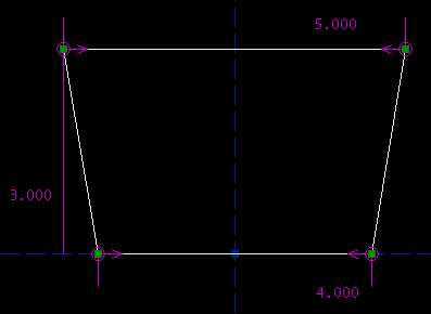
Equivalent DrawingsOf course, we could have drawn the exact same trapezoid in many other ways. Instead of finishing by constraining the trapezoid's altitude, we might have constrained its side length.
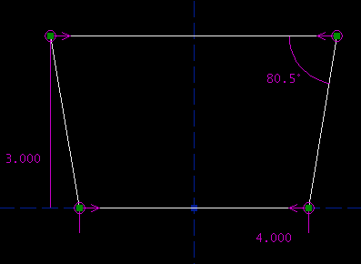
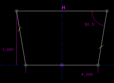
Or, we might have kept the constraint on the altitude, but replaced the top side length constraint with a constraint on one of the angles.
Or, we might not have used symmetry constraints to enforce the trapezoid-ness; instead, we could have constrained the top edge horizontal, the bottom edge's midpoint at the origin, and the left and right sides equal in length. (The magenta circle at the origin represents the at-midpoint constraint. The tick marks, which are highlighted in yellow, represent the equal-length constraint. The letter H represents the horizontal constraint.)
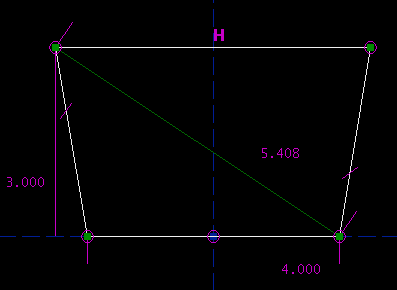
Or, we might have constrained the length of a diagonal. To do this, I added an extra line along one of the diagonals, and constrained that line's length. I don't actually want that line in my figure, though; it's just there to help me construct the geometry. To mark a `construction' line, that will not appear when you export the part as a DXF or whatever, select that line and then choose Sketch -> Toggle Construction. Construction lines are displayed in dark green.
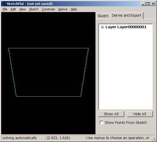
A bit of high school trigonometry will show that all of these descriptions are equivalent. We chose our initial set of constraints because they mapped well onto the specifications that we had been given. If our specifications had been given in a different form, then a different set of constraints would have been appropriate. Derive and ExportSo at this point, we've drawn the part. Click on the `Derive and Export' tab, at the top right of the window. A list of layers appears; in this case, there is only one, with its default name, Layer00000001. A more complicated sketch could have multiple layers, or `derived items' (like the Boolean union of two layers, or a step and repeat), but ours does not.
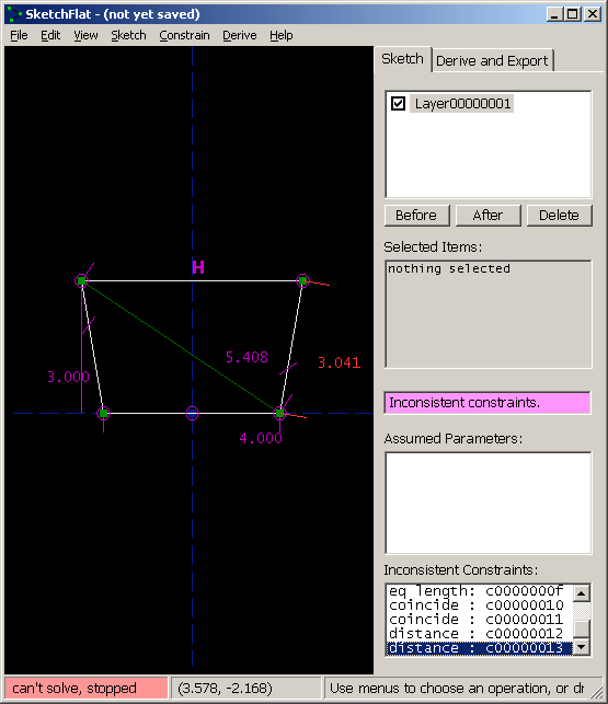
To export the part, choose File -> Export DXF or HPGL. If you choose to export a DXF, then the units will be either millimeters or inches, depending on the current display mode (View -> Dimensions in ...). If you choose HPGL, then the units are fortieths of a millimeter. If different units are required, then scale the sketch (Derive -> Scale) before exporting. The DXF or HPGL file will contain only line segments. All curves will be broken down into piecewise linear segments. The chord tolerance is determined by the zoom level of the part on-screen, at the moment that you switch from sketch mode to derive mode; zoom in more to get smoother curves. The exported file will contain all of the layers that are currently visible. (To hide or show a layer, right-click it in the list. In this case, we have just one layer, so that's not very useful.) This completes the tutorial. More complex parts are drawn by the same process, just with more entities and constraints. As the sketch becomes more complex, the program runs slower, because it takes more time to solve for all the constraints. Depending on how the sketch is dimensioned, SketchFlat can usually handle about a hundred points before it lags noticeably. Inconsistent or Nonconverging ConstraintsIn this tutorial, the sketch was always either under-constrained (when we started), or exactly constrained. There is a third possibility: a sketch can be inconsistently constrained. If we constrain the length of two sides of a square, or all three angles of a triangle, then either one of the constraints is redundant, or the constraints are inconsistent. In that case, the solver cannot satisfy the constraints, and it signals an error.
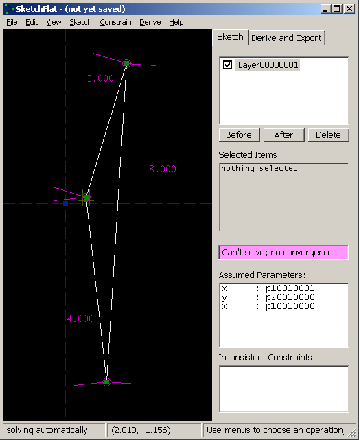
It does this in two ways: the label in the status bar, at the bottom left, turns red and says `can't solve, stopped'; and the label at the right, that is usually yellow (under-constrained) or green (exactly constrained), turns violet. At this point, the solver is off; the points are completely free, and may be dragged in such a way as to violate the constraints. It's necessary to fix the inconsistency before continuing. As a convenience, SketchFlat lists all of the constraints that, if they were removed, would make the sketch consistent again. These appear in the list at the bottom right, labeled `Inconsistent Constraints'. Once the sketch is made consistent, the solver will be re-enabled. It's possible to make extensive changes to the sketch with the solver disabled, but almost certainly a bad idea; fix the problem before proceeding. (Of course, it's also possible to make the sketch consistent again by choosing Edit -> Undo. This may be helpful if you're lost.) A related but different error occurs if a constraint is not redundant or inconsistent with other constraints, but still cannot be satisfied. In that case, SketchFlat tries to solve, but the solver does not converge to a solution. Consider the example below:
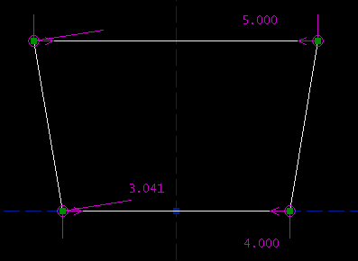
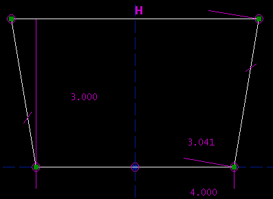
This is a triangle, with side lengths 3, 4, and 8. It's not possible to construct this triangle, because 3 + 4 = 7 < 8. The solver is therefore failing to converge. As before, it's necessary to delete constraints in order to bring the sketch back to a solvable state. It might be simpler to just hit undo. Multiple Solutions, and Initial ConditionsIt's possible to manually disable the solver, even if the sketch is consistent. This may be useful when multiple solutions exist, and you're getting the wrong one. Consider our trapezoid:
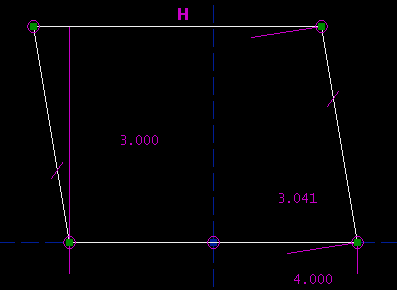
The altitude is 3.000 inches, the bottom edge is 4.000 inches long, and the left and right sides are both 3.041 inches long. SketchFlat reports that this sketch is exactly constrained, and it is. But, there are three other configurations that also meet the constraints: the sketch given below, its mirror image, and a second trapezoid.
SketchFlat decides among these multiple solutions according to how the lines are initially drawn, before they are constrained. If SketchFlat picks the wrong solution, then you can disable the solver, drag the geometry closer to what you want, and re-solve. To disable the solver, choose Constrain -> Don't Solve. To re-enable it, choose Constrain -> Solve Automatically. To run the solver once, but not re-enable it, choose Constrain -> Solve Once Now. The solver status is displayed in the status bar, at the bottom left. It's also possible to choose among multiple solutions by shift-dragging a point. This is equivalent to disabling the solver, dragging the point to its new position, and then re-enabling the solver. It's important to draw the lines fairly close to the desired geometry before constraining them. If you don't, then it's likely that the solver will find an undesired solution, or even fail to converge. It's possible to fix that after the fact, as described above, but painful in a complicated sketch. In general, it's a bad idea to draw all of your line segments, and then dimension them. Instead, draw only a portion of your part, and dimension that. Once the lines that you've drawn are fully constrained, draw more lines, and dimension those. With fewer unconstrained points at any given time, it's easier to keep track of what you're doing. This process also guarantees that the system of constraint equations will have a `nearly-triangular' structure; the solver can exploit this, and work faster. Desirability of Particular ConstraintsSome constraints are `better' than others; they have a mathematical form that makes them less prone to nonconvergence, or multiple solutions, or other surprising behaviour. Point-coincident constraints are very easy to understand. Horizontal and vertical constraints are also easy. It's better to constrain a line segment horizontal or vertical than to constrain it parallel to a coordinate axis, even though the geometric meaning is equivalent. Symmetry constraints are good. A symmetry constraint will actually write two equations, so it fixes two degrees of freedom. This means that each symmetry constraint fully constrains one point, which often makes the sketch easier to understand. Point-to-point distance constraints (which include constraints on the length of a line segment) are good, but they typically produce multiple solutions; draw your lines fairly close to the desired geometry before constraining them. Equal length constraints are similar to point-to-point distance constraints. Equal radius constraints are either similar to point-to-point distance constraints (for arcs), or easy (for complete circles). Point-to-line distance constraints are good. They do not tend to produce multiple solutions, because these distances are `signed'. If a point is constrained to lie 20 mm above a horizontal line, then the solver will reject the solution where the point is 20 mm below the line. (Internally, the distance is either positive or negative. The sign is not displayed on the sketch, but you can move the point to the other side of the line by typing a negative distance.) Line-to-line distance constraints are equivalent to point-to-line distance constraints. Line-line distance is meaningful only if the two lines are parallel; it's necessary for some other constraint to enforce that. Point-on-line is equivalent to point-line distance with a distance of zero, so that's good too. Angle constraints are trickier, and more prone to unexpected behaviour. Parallel and perpendicular constraints are special cases of angles. Angle constraints apply modulo 180 degrees, and their sign is not shown on the sketch. This means that a 135 degree angle is equivalent to a 45 degree angle. It's arbitrary which number is displayed on the sketch; to switch, select the constraint and then choose Constrain -> Other Supplementary Angle. (The angles are signed internally, though. As with the point-line distance, you can type a negative number to flip the sign.) If we wanted to draw a rectangle, then we would draw four line segments, that form a closed polygon. We could then constrain them, using:
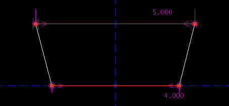
Example to DownloadYou can draw it yourself, but this is our trapezoid:
December 2007, near Seattle |