|
PCB Router |
||||||||||||||||||
|
Printed circuit boards are usually manufactured by chemical etching (with iron (III) chloride or ammonium persulfate, for example). This is not very practical if only a few boards are necessary, because these etchants are messy and somewhat dangerous. PCBs can also be manufactured by "mechanical etching," in which a trace is "etched" by milling away the copper along its perimeter. This requires software to generate a toolpath from the layout and a small CNC mill or router. Lots of companies make routers for PCB fabrication, but they are unjustifiably expensive so I decided to build one.
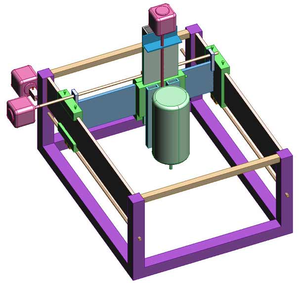
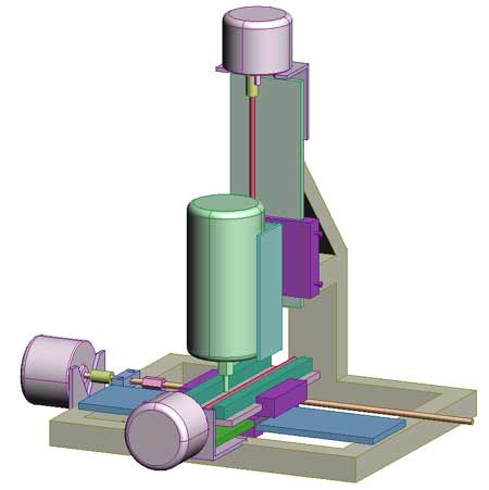
My first design was a sort of bastard gantry mill. The workpiece was stationary; the spindle was bolted to the z-carriage, which travelled along the z-ways (grey), which were bolted to the y-carriage, which travelled along the y-ways (cyan), which were supported at either end by two x-carriages. Each carriage was driven by a screw; each screw was driven by a stepper motor, so that the x-motors were stationary, the y-motor moved in the x direction, and the z-motor moved in the x and y directions. This was an extremely poor design. The biggest problem was probably the alignment of the x-ways; I suspect that they would have had to have been very close to parallel (thousandths of an inch over their length) or the carriages would have tended to jam. Lucky for me there were so many other problems that I never found out whether that was true. The bearing for the y-screw was mounted to one of the x-carriages, not to the y-ways; that meant that if one x-carriage got ahead of the other then the y-screw would become misaligned and bind. There was really no place for the stepper motors. The drawing shows them floating in space because I assumed that the mounting would be obvious once the screws were in place; it was not. It has subsequently been pointed out to me that it is easy to avoid the parallelism problem—constrain one side of the gantry so that it has one degree of translational freedom, but constrain the other so that it has two degrees of translational freedom and one degree of rotational freedom. Commercial engraving machines achieve this by supporting one end with a rod inside a linear bearing and the other with a rod clamped between three rollers.
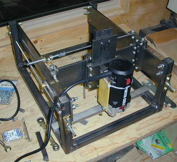
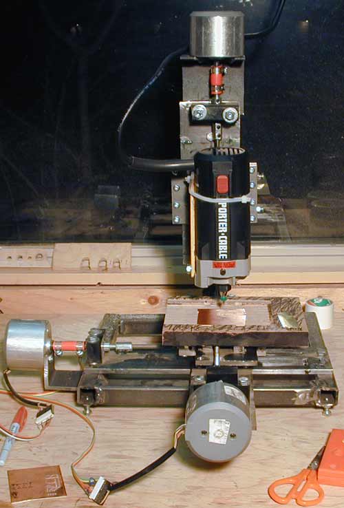
And so I got out my cutting torch and I started over. I was more conservative this time; I decided that the workpiece would move in the x and y directions and the spindle would move in the z direction (as in most real milling machines). I was able to reuse the slide mechanisms from the initial design, but that was about it. The spindle is a Porter Cable laminate trimmer. The one I bought has about 0.001" runout in the spindle, which is acceptable and probably better than a Dremel etc. It also has a convenient 1/4"-20 hole tapped in the base. It is horribly loud, unfortunately. It accepts 1/4" bits. Most small drills and end mills have an 1/8" shank, so I purchased a bushing at Lee Valley.
The laminate trimmer is screwed to the motor mount. Since there was only one tapped hole in the trimmer and I was reluctant to mutilate it, I used cable ties to further secure the laminate trimmer. This is much more solid than it sounds. The motor mount attaches to a carriage (z-carriage) which slides along 3×1/4" CRS ways (z-ways). The slides are all crude box slides assembled from CRS. The work table is made from MDF. It is screwed to the y-ways. The y-ways travel in the y-carriage. The y-carriage is bolted to the x-carriage. The x-carriage travels along the the x-ways, which are bolted to the frame.
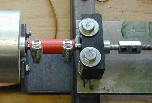
The green stuff in the above picture is ordinary grease. The shop where I work is heated with a propane construction heater so there tends to be a lot of moisture in the air. I was worried that the slides would rust so I lightly coated them with grease. This was not smart—the grease mixed with the MDF dust to form a sort of glue, and it mixed with the FR-4 dust to form an abrasive paste. The slides became progressively stiffer; I eventually had to completely disassemble the machine and clean everything with mineral spirits. I now use a fluoropolymer dry film lubricant. This is much better; it still provides some protection against rust and it does not attract dust. The screws are 1/4"-20 rolled V-thread threaded rod. They turn in brass nuts. Originally there was less than 0.001" backlash in the y direction, which was surprisingly good. There was about 0.015" backlash in the x direction, which was rather bad. I suspect that I used the tap drill for 50% thread engagement when I made the x-nut. I was able to reduce the backlash in the x direction to less than 0.001" by remaking the x-nut with the correct (#7) size drill. The nuts have since worn a little bit; now I get about 0.004" backlash in each direction. This isn't terrible considering that I don't usually work with anything smaller than SOICs (0.050" pin spacing), but I still compensate for the backlash in software. All the backlash in the z direction is taken up by the weight of the router. The screws are coupled to 1/4" bolts with their heads cut off. The unthreaded portions of these bolts turn in ball bearings (a thrust bearing for the z axis); set screw collars stop the shafts from sliding through the bearings. The shafts are coupled to the stepper motors with plastic air hose, which provides a little bit of U-joint action to help compensate for slight misalignment between the bearing and the motor. The ball bearings are the deep-groove type so they can accept a slight misalignment between the bearing and the nut. The bearings are mounted in black polypropylene blocks. For the x and y axes, the holes that accept the bearings are slit so that the bolts that hold the polypropylene block in place also tend to clamp the bearing in place. This is necessary because polypropylene is rather springy and weak (so that a press fit is not really practical), and because I am not equipped to produce an accurate 0.750" hole. I just used a spade bit, but the bolts clamp the bearing quite securely. The block that supports the z-bearing is basically just a shelf with a recess for the bearing and a 5/16" hole in the bottom to allow the 1/4" shaft to pass through.
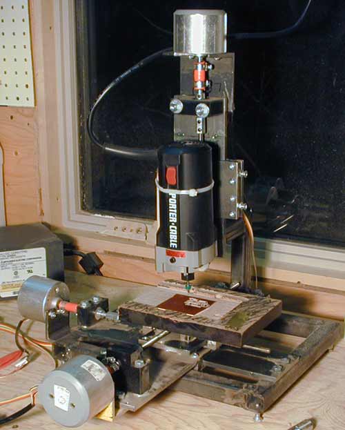
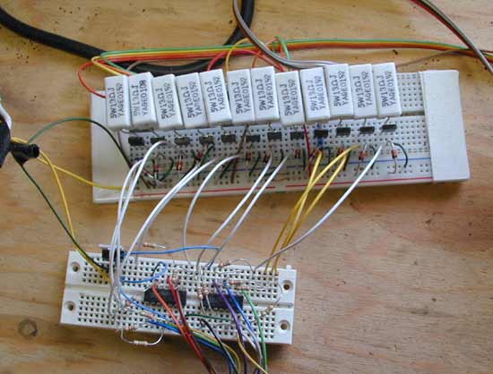
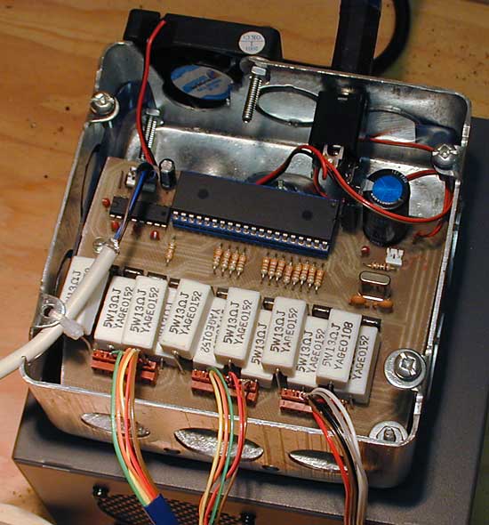
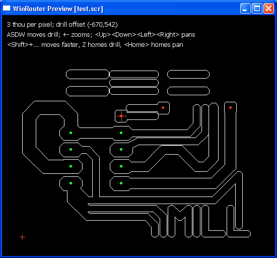
The stepper motors are from Active Surplus. I run all three of them from a 14 V 5 A switchmode power supply. Originally I just bit-banged the waveforms into the parallel port of an old Linux box. The parallel port outputs drove some buffers (the small breadboard), which controlled some big power MOSFETs (the black things on the large breadboard). The white components are power resistors; a resistor in series with the stepper winding will keep the current closer to constant with switching frequency (as the winding is inductive). The little red components are diodes to catch the back-emf. This controller worked, but the stepping waveforms were generated from a user-space Linux program so the timing wasn't very predictable. This meant that I couldn't run the steppers faster than they could go starting from a dead stop, as my program might lose the CPU (stopping the stepper motor) for milliseconds or worse. The right way to run the stepper motors is from a dedicated CPU. I built a controller around a PIC16F877. It talks to the PC over RS-232 serial. I control the steppers by toggling GPIO pins on the PIC. This means that I can ramp up the speed without worrying about losing steps (as I am in complete control of the timing on the PIC). I used my bit-banged controller to mill the board for this one. It runs pretty hot. The MOSFETs dissipate virtually nothing but the power resistors burn about 5 W each, for a total of ~30 W given that two phases per stepper are energized. The fan seems to help a lot. I draw my layouts in EAGLE. EAGLE comes with a tool to generate the outline of each trace in a layout. I use that tool to turn the layout into the outline of the layout. EAGLE can also generate Excellon drill files. Once I have the outline and the drill file I can preview them using a tool that I wrote:
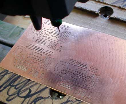
If the preview looks right then I'm ready to mill. At first I used broken-off drill bits for end mills. They worked better than you'd expect, but that's not saying much. I attach the copper-clad board to the work table with double-sided carpet tape. I set the cutter height by placing a scrap of 0.002" brass shim stock on top of the workpiece and lowering the router until I feel a slight drag on the shim stock when I slide it in the x and y directions.
My software then mills around each trace. When it is done it raises up the router so that I can remove the "end mill" (i.e. broken-off drill bit) and install an (unbroken) drill bit. It's very likely that the router or something else will move slightly during this operation so after changing tools I have to put the drill bit above the first hole to be drilled. This hole is indicated with red crosshairs in the previewer. The software then drills each hole specified in the Excellon file.
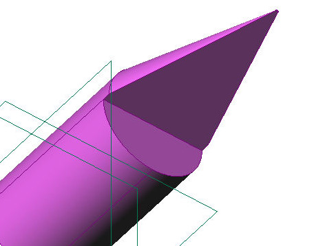
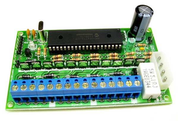
I have since purchased better milling cutters. The cutters that I now use are made by New Hermes and presumably intended for some sort of engraving task. They are made from 1/8" rod and appear to be solid carbide. The cutter geometry is approximately as pictured above. Of course these work much better than some scrap of pcb drill that happens to have a sharp edge; these cut a clean, burr-free trough through the copper foil. A machine like this really should be built with linear guides and ballscrews. Unfortunately I have no idea where I can find cheap mechanical components locally. Some of the software, schematics, board layouts etc. are available here. I also have some rough sketches of the mechanics in Pro/Desktop format, but I do not know of any free tool that will open these files. * * * To be honest, I have never used it much for PCBs. Most of my boards include at least one part that is only available in a TSSOP or a 0.5 mm pitch LQFP/TQFP. That is not very easy on a milled board. I have seen it done, but I am not about to try. I find the router very convenient for small plastic parts; you can make all sorts of things by milling them from Lexan sheet. I use an 1/8" spiral router bit designed for use in wood, and it works very well; I cut 6 mm sheet in a single pass, and it leaves an excellent surface finish. The only trick is to get the feed right. Too fast and I lose steps, but too slow and I melt my way through. * * * Someone wanted to do a kit of a controller very similar to the one pictured above. I ended up designing this:
It's basically the same as the one on the milled board, except that it is missing the power resistors. It is also missing the MAX-232, so you have to drive it from TTL-level serial, not RS-232 serial. The project never went ahead, but I ended up with a lot of parts and boards for free. Since April 2003, Waterloo |