|
|
An LDmicro Tutorial |
|||
|
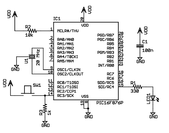
(also in: Italiano, Deutsch, Fran�ais, Русский) In this tutorial, I will show you how to write a very simple program. I am assuming that you have written ladder logic before, and that you have some basic familiarity with microcontrollers, but that you have never used LDmicro. If you don't know very much about ladder logic or PLCs, then the plcs.net tutorial might be helpful to you. Our device will have one pushbutton, and one LED. At startup, the LED will be off. When you press the pushbutton once, the LED will turn steady on. The second time you press the pushbutton, the LED will start blinking. The third time that you press the button, the LED will turn off again. On subsequent presses, the cycle will repeat. Microcontroller Selection and SchematicWe will be using a PIC16F876, which is easily available from Digikey or other online distributors. It comes in a number of different packages; I chose a DIP. Note that as of Nov 2009, the PIC16F876 is no longer recommended for new design. This means that it will probably get discontinued at some point in the next few years. You may prefer to instead use a PIC16F886, which is pin-compatible. If you do, then make sure to specify the correct part when you compile, since the 'F886 is not code-compatible. This is our schematic:
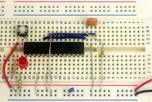
The microcontroller (IC1) is part number PIC16F876-20I/SP-ND at Digikey. Almost any three-terminal resonator (U1) will do; you might try a 535-9356-ND or an X909-ND. The only thing that might confuse you is that the pushbutton goes to Vdd, and there is a pull-down. You might be more used to seeing a pushbutton to ground with a pull-up. For TTL, this mattered. For modern CMOS it does not, and I find this `active HIGH' arrangement less confusing than the traditional `active LOW' circuit. Also, I chose to use a ceramic resonator with internal capacitors, U1, instead of a crystal and two ~20 pF caps. A crystal would work just as well and it would be more accurate, but it would be a little bit more expensive, and you would need more parts. You could build this circuit in many different ways. I built it on a solderless breadboard, and it ended up looking like this:
(The resistor values pictured are not quite the same as the schematic; none of them are critical.) Ladder Diagram for the ProgramFirst, we are going to need an oscillator to generate the `blinking' signal for the LED. There is a standard way to do this in ladder logic:
         ||      Rosc            Tosc_on         Tosc_off           Rosc       ||
       1 ||-------] [--------[TON 250.0 ms]---[TOF 250.0 ms]---------(/)-------||
This will flash at 1/((250+250) ms), or 2 Hz, or twice per second. The duty cycle will be 50%—250 ms on, then 250 ms off. This circuit can make any kind of oscillator, with whatever period or duty cycle you require, so it is a good one to remember. Also notice that we have chosen to use an internal relay (`Rfoo') instead of one attached to an I/O pin (`Yfoo' or `Xfoo'). This makes sense, because there is no particular reason to bring that signal out to a pin. LDmicro will automatically assign memory for the internal relay. Our program will have three states: off, steady on, and blinking. The program should change its state on each rising edge of the signal from the pushbutton. This is a good application for a circular counter. We will say that `state 0' is `off,' `state 1' is `steady on,' and `state 2' is `blinking.' The counter counts 0, 1, 2, 0, 1, 2, ..., so if we just let the rung-in condition of the counter be the pushbutton input, then everything will work like we want:
         ||     Xbutton                                            Cstate      ||
       2 ||-------] [---------------------------------------------{CTC 0:2}----||
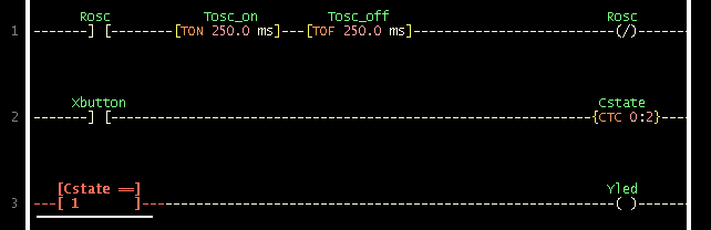
Now the only thing left is to use the program state to set the state of the LED. We can do it like this:
         ||   [Cstate ==]                                           Yled       ||
       3 ||---[ 1       ]-------------------+------------------------( )-------||
         ||                                 |                                  ||
         ||   [Cstate ==]         Rosc      |                                  ||
         ||---[ 2       ]----------] [------+                                  ||
It should be easy to convince yourself that this does what we want. If the program is in state 1, then the `Cstate == 1' instruction energizes `Yled', as desired. In state 2, the `Cstate == 2' instruction energizes `Yled', but only when `Rosc' is also true. Since `Rosc' is oscillating, that means that the LED will blink, as desired. Finally, in state 0, neither of the equals instructions will be true, so there is no way that `Yled' could ever turn on. Entering the Ladder DiagramNow that we have our circuit, we can draw it in LDmicro. When you start LDmicro, you will see a single empty rung:
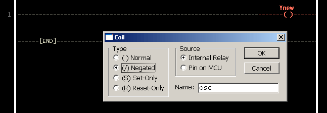
We want to enter the first rung from the listing above. We will start with the coil, so choose Instruction -> Insert Coil. This will create a coil named `Ynew.' This is what we want, except that the name is wrong, and it should be negated. Double-click the coil; this will bring up a dialog where we can fill that in:
Now we can insert the rest of that rung in the same way. Click on the left edge of the coil, so that the cursor is vertical, and to the left of the coil. Now choose Instruction -> Insert TON (Delayed Turn On). Once again double-click the timer to rename it and set the period. Add the TOF timer and the contacts in the same way. Now we want to enter the second rung, so choose Edit -> Insert Rung After. Then click on the second rung to move the cursor there:
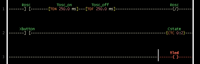
The second rung is easy: just fill in the two instructions in the right order, by placing the cursor where you want to insert and then choosing Instruction -> Insert .... Remember to assign a name (`Xbutton') to the contacts, and to set the name and upper limit of the counter. Then choose Edit -> Insert Rung After again. Your program should look like this:
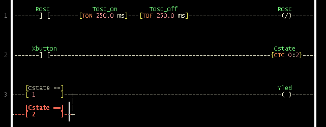
The third rung will be a bit trickier, because it has parallel branches. That means that you have to think about the order in which you insert the instructions. First, insert the coil, and rename it:
Now insert the first equals instruction to the left of the coil, as usual, and fill in the correct variable name and value. After you do that, add the parallel branch. You can do this by clicking on the bottom edge of the equals instruction; the cursor will be horizontal and below that equals instruction:
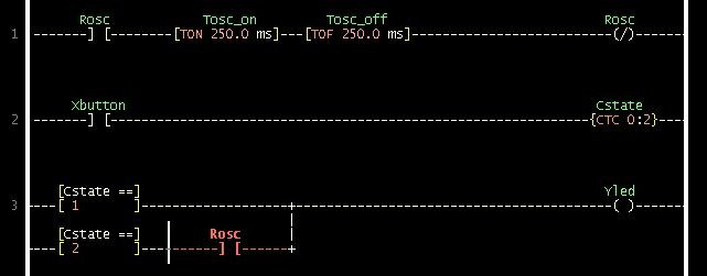
Now choose Instruction -> Insert EQU (Compare for Equals). Since your cursor is below the first equals instruction, the new equals instruction will be inserted below that instruction, in parallel with it. Rename it as usual. To finish the rung, you must insert the `Rosc' contacts to the right of the second equals instruction. To do this, click on the right edge of the second equals instruction:
At this point you can choose Instruction -> Insert Contacts; the contacts will be inserted in series with the second equals instruction, as you require. Rename it and you are done:
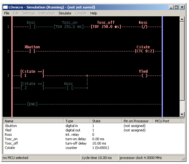
Simulating the ProgramNow we are ready to simulate our circuit. Choose Simulate -> Simulation Mode. The display will change; the ladder diagram will appear mostly greyed, but you won't see anything changing with time. That is because the PLC is not yet cycling. To start it cycling, choose Simulate -> Start Real-Time Simulation. Now you will see things happening: the oscillator is obviously running, but the LED (`Yled') is still off, which is what we want, because no one has pressed the button yet. To simulate pressing the button, double-click the text `Xbutton' in the list at the bottom of the screen. You have now simulated bringing the pushbutton input high; this is what would happen if someone depressed (but did not yet release) the pushbutton.
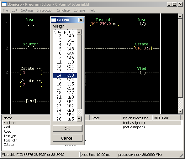
You can see that the program is working: the `Cstate' counter is now equal to 1, which corresponds to the `steady on' state, which is what we want. The LED output is high; you can see that its value is 1 in the list, and the `Yled' coil appears red on the diagram. Double-click the `Xbutton' text in the list to simulate releasing the button, then double-click it again to simulate pressing it again; the `Yled' coil will start blinking, as designed. If you simulate a third button press then the output will go steady low. Compiling to an IHEX FileSo now we are fairly sure that the program works. At this point we are ready to generate actual code, and try it in the micro. First, exit simulation mode by choosing Simulate -> Simulation Mode, or by pressing Escape. Next we must choose a microcontroller. We decided earlier that we would be using a PIC16F876, so choose Settings -> Microcontroller -> Microchip PIC16F876 28-PDIP or 28-SOIC. We also have to tell LDmicro what kind of crystal we will be using, and what the cycle time will be. Choose Settings -> MCU Parameters, and fill in our clock speed of 20 MHz. Leave the cycle time at 10 ms; that will usually be a good value. Now we can assign pins to our inputs and outputs. Double-click `Xbutton' in the list at the bottom of the screen, and choose pin 14 of the PIC, which corresponds to MCU port RC3. (There is usually no reason for you to care which port you are using; just look at the pin number.)
Click `OK,' and then repeat the process for `Yled', which you can see from the schematic should go to pin 15. The other elements in the list are internal variables and bits in memory, so there is no need to assign pins to them. LDmicro will allocate memory for them when you compile. So now you are ready to compile. Choose Compile -> Compile, and specify where you want to put the IHEX file. Then use whatever PIC programming equipment you have available to load that into your device, and you are ready to try it out. This completes my tutorial. It is possible to write much more complex programs than that, of course. A program this simple uses only a very small fraction of your processor's memory, so there is room for many more rungs of logic. LDmicro also offers specialised instructions, for things like arithmetic, analog (A/D) inputs, PWM, and even text output to a character-based LCD. Consult the manual for details. I don't see why you would need to, but you can download the tutorial program premade. November 2009, near Seattle |