|
Proximity Cards |
||||||||||||||||||||
|
[There is a better device, although the writeup for this one is longer. It took me a month of evenings to clone my first Flexpass, with basically no equipment. Using my latest hardware, I was able to clone a Verichip—which, like the Flexpass, is an ID-only tag with no security—with only a few hours' work.] * * * Lots of companies use proximity cards to control physical access. An employee holds their card within a few inches of the reader; the reader receives a unique id from the card and transmits it to some central computer that tells it whether or not to open the door. This is rather magical, considering that the tag is credit card-thin and contains no battery. The trick is the same as for RFID tags. The reader constantly transmits a rather strong carrier; the tag derives its power and clock from this carrier, kind of like a crystal radio. The tag changes how much carrier it reflects back at the reader—loosely, it makes the circuit across its antenna more like a short or more like an open—to transmit its code. The reader and the tag both have antenna coils tuned to the carrier frequency; they work like a loosely-coupled resonant transformer. Or at least that's the theory. I couldn't find any credible documentation on the protocol used by the particular proximity cards that were available to me (Motorola's Flexpass). I did find a datasheet that claimed that they worked with a 125 kHz carrier. I wound a couple dozen turns of magnet wire on a 4" form, taped it to a reader, and 'scoped the coil. There was indeed a 125 kHz sine wave, large, a few volts peak to peak. The cards did, at least, work at 125 kHz. A Card ReaderThe next step was to build a reader. The reader must transmit a fairly powerful carrier; figure at least tens of milliamps through a coil of about a millihenry. This is easy: just blast a 125 kHz square wave into the reader coil. It's a tuned circuit so it will pick out the 125 kHz component very nicely. Then, we want to look for slight (at least 40 dB down) changes in the coil current. We do this by sampling the voltage across the tuning capacitor and feeding it into a detector circuit. Tags can use lots of different modulation schemes—PSK, FSK, plain AM. I decided to build an AM reader, assuming that that was the most likely modulation scheme, and that if the cards used something else then I could probably do the detection in software.
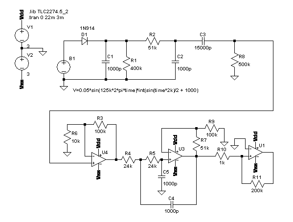
B1 models the voltage on the reader cap when the tag is backscattering a 1/π kHz square wave. D1 and C1 form a leaky peak detector, producing a 125 kHz sawtooth whose peak is determined by the peak value of B1 during that cycle. R2 and C2 are a low pass filter, to even out the sawtooth quality of our measured amplitude. C3 and R8 AC-couple the signal down to ground; otherwise it would be hard to work with because its average value is around the amplitude of the sine wave, which will be around a hundred volts (V = IZ = IjωL = (50 mA)×j2π×(125kHz)×(1.6 mH)). U4 buffers the signal and amplifies it a bit. U3 is a Sallen-Key low-pass stage. U1 is a comparator, to turn the measured amplitude into something that can drive a digital input. R10 and R11 add hysteresis, which later turned out to be very important. I don't think there's anything very novel about my circuit. I realized from a Microchip app note that the key is to start with a peak detector. I later found Microchip's reference design for an ASK reader. It's fairly close to mine: peak detector, passive low-pass, AC couple it down, active low-pass, comparator.
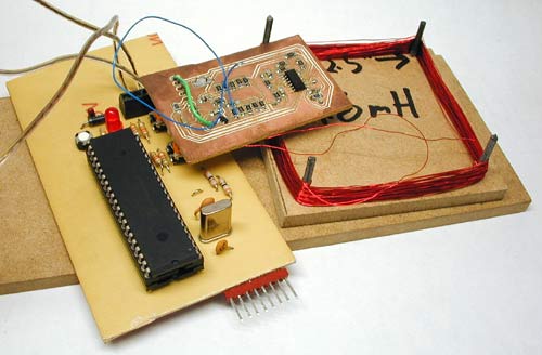
I built the reader on two printed circuit boards. The largest one contains a PIC16F877, used to generate the 125 kHz square wave, and the circuit to drive and tune the coil. The reader coil is a ~1.6 mH inductor wound from about 140 turns of 30 gauge magnet wire on a 2.5" square form. The smaller board implements the detector circuit shown above. Both are single-sided boards made on my milling machine. So I placed a Flexpass card on top of my reader coil, and I watched the output. Sure enough, I got modulation; alternating positive- and negative-going pulses, unevenly spaced, like what you'd get if you took a serial bitstream and high-pass filtered it. This was very encouraging. A Card SimulatorI designed a tag that could produce identical AM when I tested it against my reader. This was pretty boring. I used a micro and alternately tri-stated or asserted (one low, one high) two GPIOs connected to one terminal of the tuned coil, with the other antenna terminal grounded. My tag produced perfect waveforms on my reader. It did not, however, work with the Motorola readers—the door did not open.
So then I tried a lot of things. Eventually I took a closer look at the output of the peak detector; it was a 62.5 kHz sawtooth, not 125 kHz. The card was transmitting PSK, attenuating every other peak, but my peak detector didn't drop fast enough to follow it. The AM that I saw was a modulation artifact; I expect (and it's intuitive) that it can be shown that those sorts of amplitude variations can be obtained by bandpass-filtering a PSK signal.
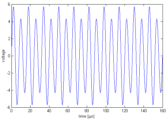
A bit time is 256 μs. The tag's id is periodic over 64 bit times, 16384 μs. When there is no phase shift, the signal is a 125 kHz sinusoid slightly modulated by a 62.5 kHz sinusoid. The modulation is greatly exaggerated in the figure.
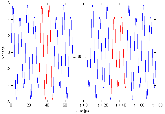
To indicate a bit transition, the tag inserts a phase shift of π. There is always an even number of carrier cycles between phase shifts, so that if the most recent phase shift was achieved by skipping a small-amplitude cycle then the next phase shift will be achieved by skipping a large-amplitude cycle.
Since a bit time is 256 μs, phase shifts are an integer multiple of 256 μs apart. Thus, in the above picture, we could have t = 256, 512, 768, ... μs. A code consists of 64 bit times. There are no transitions for the last 29 bits for all but one of the cards that I have tested. Possibly the one card is in a newer format, or possibly it's just weird. There appears to be some structure within the bits—if I get some of the bits wrong then the reader doesn't even beep, but if I get others wrong then the reader still beeps but the door doesn't open. I haven't had any need to figure out which are which though. My first tag sort of disintegrated (too many flywires) so I built a new combination reader/tag. In tag mode I chose to ignore the reader's carrier: I just blast my own modulated carrier at the reader. This works perfectly well, and you'd expect it to; if we're not in phase with the reader's oscillator then we will be in a few hundred milliseconds. (The beat frequency is ~1 Hz, for a variation of a few ppm, typical for a crystal). A Toy With Blinking LightsThe hardware to pretend to be a tag is very simple. The hardware to read a tag is not much more complicated; I could do it with a micro, a quad opamp, and a dozen passives. This meant that I could build a combination card reader/simulator in a few square inches of board space. Add a couple of lithium batteries and some nice plastics and I would have a clever and mostly useless pocket-sized toy. Of course I couldn't resist building it.
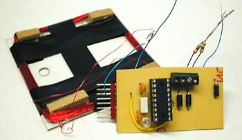
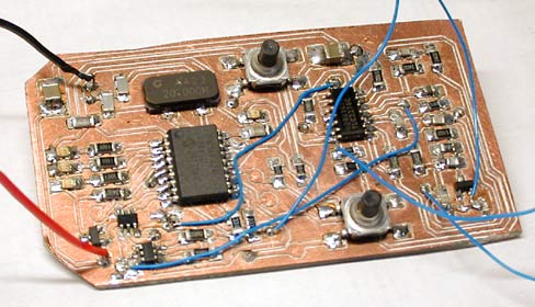
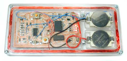
For a sense of scale, the PIC16F628 (largest IC) and the opamp are both SOICs. There aren't any unreasonably fine-pitch components on this board; the tightest are the SuperSOT FETs (bottom left), with 0.95 mm lead spacing. The hardware is very similar to the larger reader/simulator described above. I decided not to attempt PSK demodulation; I just detect the modulation artifacts and use the hysteresis, so that I know that if the comparator output has changed state since I looked at it last then there has been a phase shift since then. This sacrifices a bit of sensitivity but my read range is small enough (by design, for reasonable battery life) that this doesn't bother me. This hardware could also be used for AM cards, if I ever came across one. The PIC can kill power to the detector section with a couple of FET switches. This plus the PIC's sleep mode means that I can do on/off in software without ruining my battery life. The circuit is again built on a milled PCB, with one signal layer and a ground plane. The ground plane is split into analog (GND = 0V) and digital (V- = -3V) sections. It is powered by a pair of CR2032 lithium coin cells. They determine the thickness of the device; the batteries, in a holder, are 0.217" thick.
There are no connectors on the board because I couldn't find any low-profile surface mount connectors that I liked. Instead there are test points to program the PIC and tune the coil; I actually built a test/programming fixture (with pogo pins). This is pretty easy with a CNC machine. Power and coil leads are soldered directly to the board. The blue wires are mostly test points, for debugging only. The 8 pin header connects to my PIC programmer.
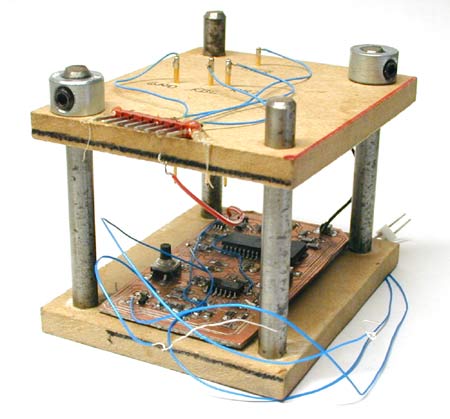
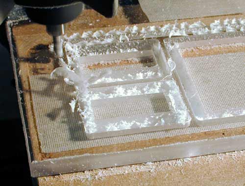
All the plastics were routed from sheet on my milling machine, using an 1/8" carbide straight bit intended for use in wood. Yes, the workpiece is held to the table by carpet tape; this is much cheaper than a vacuum chuck.
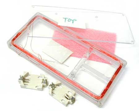
The top and bottom of the case are each 1/16" Lexan (polycarbonate); the core is milled from 6 mm Lexan sheet. The top has drilled holes for the actuators of the two tact switches on the PCB. I paid too much (more than a dollar each!) for the battery holders shown below because they make it very difficult to apply a reverse voltage to the circuit by mis-inserting the cell. The pink foam presses the board into contact with the lid so that the tact switch actuators project.
Both the top and bottom screw into the core with #2 tapping screws. I put a lot of effort into finding a local source for a methylene chloride solvent cement (so that I could weld the bottom on instead of screwing it) but I gave up after many failures. I first tried machine screws but small-diameter machine screws tend to have too many threads per inch to work in plastics. Next time I'd probably look for threaded inserts.
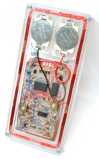
I left the wires long so that I can remove the the board from the plastics without desoldering anything. This is necessary to put it on the programming jig, and it helps when I'm trying to figure out whether I have a circuit-does-the-wrong-thing problem or a 125-kHz-pickup-on-everything problem.
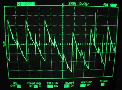
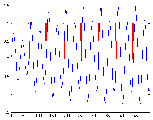
The user interface comprises four LEDs and the two tact switches. The software can currently read a card, store a single id, transmit that id over the air to a reader, blink out that id on the LEDs, and accept a new id on the tact switches. There is also a “sniff” mode, in which the detector is active but the coil is not powered; this allows me to read a card while a legitimate reader is powering it. (The read range of the cards is limited by the tag power requirements, not by reader sensitivity; it goes up substantially when another reader is powering the card.) Most of the software is pretty straightforward. To transmit the id, I must apply a square wave with, on average, every other cycle missing. I do this entirely in software, flipping a GPIO every 4 μs. I managed to make this work on a 4 MHz device (4 cycles between edges); it's much easier on a 20 MHz device, though. The antenna is resonant around 125 kHz, so that it effectively bandpass filters the pulse train that I generate. In the figure below, the blue trace is obtained by passing the red trace through a bandpass filter centred at twice the frequency of the pulse train:
For the reader functionality I configure the PWM module to generate the unmodulated square wave so that I can be a bit sloppier with my timing. I sync on the word by waiting for an edge after a long idle period (though this is of course unnecessary; I only need bit sync). Then I read the word into memory. Then, I read the word ten more times, comparing it against the recorded copy each time; if they all match then I decide that it's right, else I lose sync and try again. This works reasonably well, but if the card is held just barely outside the read range then I will eventually false-sync. This is bad, because there is no other verification. Legitimate readers can false-sync with no major repercussions, since they would just fail to open the door; the user would stand there waiting until the card was read correctly. Security ImplicationsI can copy a proximity card at least as easily as I can take an impression of a key. This means that it's not a very good idea to reuse visitor cards without changing the id (and that it doesn't really matter whether you get the physical card back from the guy you just fired). More insidiously, it's quite practical to read someone's card without removing it from their wallet. A bit of deliberate clumsiness, a reader up my sleeve, and I would have little trouble cloning anyone's card. I could also exploit the fact the distance at which the cards will be powered is less than the distance at which they can be read; if another reader is exciting the card then my reader can read that card from the other side of a wall! This means that a sniffer concealed somewhere near a legitimate reader could intercept real transactions at a significant distance. This sort of attack is particularly good because the card repeats its id over and over as long as it is in the field, so that I could use signal processing techniques to combine multiple copies of the pattern to further improve my read range. This is easy—if I sample all 64 bits of the id then I don't have to get word-sync, and if I oversample then I don't even have to get bit-sync. Even if I capture the id with a few bit errors it is still useful; I could try the captured id, then every id with a Hamming distance of 1 from the captured id (one bit flipped), then 2, and so on. One or two bit errors would take seconds; three would take minutes. If I were willing to spend money on a four (or even two) layer board then I could build a sniffer/reader much smaller than anything shown above. If I used black Lexan (or even acrylic) for the case then the device would look less like something that an image-conscious terrorist might carry. This would make it much easier to carry out the attacks outlined above. All of these attacks can be stopped with a challenge/response scheme. I've seen brochures for cards and readers that do this; I guess it's not just a marketing gimmick. Hardware NotesThe coil driver consists of an N/P FET pair, with the FETs working as switches. For my initial reader I connected the drains together, like in a CMOS inverter. This drove the RLC circuit that was the coil, the tuning cap, and a current-limiting resistor. This has two flaws. First, it has a software self-destruct mode; if the input floats between the positive and negative rails then both FETs will conduct, shorting V+ to V-, and the FETs will get very, very hot. This caught me because the PIC tri-states all its GPIOs when it's being programmed in system. There was a bit of a shoot-through problem too; the switching transients got in to everything. Smaller FETs would actually have been better, but I just put some resistance between the drains, because I needed some resistance to limit the current anyways. My layout seems to be reasonably good. There's hundreds of millivolts of noise on most of the signals around the PIC, but noise on the detector signals is in the tens of millivolts. More bypassing might have cleaned things up further. Not placing the circuit inside the antenna might also have helped.... The detector is rather poor. When reading (or sniffing) from a large distance, it would be nice to be able to turn down the hysteresis to get some chance at a read. This is not currently possible. It's probably not worth messing with the envelope detector though; it would be better to build a proper PSK detector (by correlating and then integrating the peak detector output in hardware, or with a sharp notch filter to reject the 125 kHz component, allowing me to work only with the sidebands.). The coin cells probably aren't a very good choice for this application considering the high peak currents—Panasonic's datasheet doesn't even mention what happens if you try to draw more than a milliamp. I don't know what would be better, though; thin batteries are hard to find. The opamps that I use (TLC2274s) are not low-current. I knew this when I chose them but I assumed that they would only need to be powered when the coil was energized. In sniff mode this is not true; the coil is not driven, and I could even put the PIC to sleep and wake on an edge from the detector. Next time, I guess. I was careless when I designed the power switching stuff; there were a couple of leakage paths that added almost 60 microamps of off current. I was able to fix this by depopulating a couple of components and faking out the functionality that they used to provide in software. Off current is about 4 μA. The CR2032s can deliver about 200 mAh, for a standby life comparable to the shelf life of the cells. The presence of metallic objects inside the antenna probably does weird things. Certainly it detunes the coil a bit, and even after I tweaked it back to resonance the voltage on the coil was smaller (indicating that some of my battery life is going to eddy currents in the mounting screws). I had a few interesting problems relating to 125 kHz pickup from the read coil. The wires from the board to the coil are quite vicious; seriously bad things happen if they rest on the analog traces. I had a lot of trouble machining the polycarbonate until I got my feeds and speeds right. Too slow of a feed for your speed is very bad; the plastic melts, the cutter loads, friction increases and chip ejection goes to nothing, and you get thermal runaway. Once I figured that out everything went quite easily. Surface finish with an 0.015" finish pass was acceptable as machined almost everywhere. Where it wasn't I used the non-serrated edge of a hacksaw blade to clean it up. Acrylic makes a nicer case than polycarbonate—it's more rigid and less prone to scratching. An acrylic case probably wouldn't survive a two foot drop onto concrete, though. Future PlansThe toy described above is nice, but it could be better. I believe that I could sample the peak detector output directly (after AC-coupling it down) and do the demodulation in software. I have a very clever idea that uses the PIC's comparators and voltage reference module to do PSK detection, possibly one so clever that it works only in simulation. This would allow me to lose the opamp entirely. I could drive the coil from a few GPIOs tied together, at the cost of read range. This would get the design down to the micro plus some passives. I'd also like to get rid of the split supply and run from a single 3 V rail. I think I'd have to do some sort of trick with multiple coils (like a transformer) to get a reasonable input impedance without an unreasonably high Q. Alternatively, I could build a long range sniffer (better detector, one foot diameter read coil, enough current that it's just on the edge of melting, a motorcycle battery to power the thing...). This wouldn't be nearly as cool as a smaller version of my toy but it would be better for convincing people that the cards are insecure. October 2003, Waterloo |